330 Volt
Disposable Camera Stun
Gun
This
is a 330 volt stun gun, well more of a shocker, it doesn't actually stun like a real stun
gun as it simply does not supply enough voltage. Real stun guns can supply approximately
300,000 volts!
Nevertheless, this device can still give a surprisingly intense shock to
someone. I did not make this device to be used as
a self defense item or to inflict harm other people, I simply thought that it
would be a fun and interesting
project to undertake; and that it would be fun to use with friends.
This can potentially harm a person if they are old or have a heart condition for example. This is a great project
that is simple providing you have a basic knowledge
of electronic devices, tools and equipment.
Theory behind
the device
Before attempting this project I advise you to get a good background knowledge
of how the device is going to work and how the components within the device also
work.
This device uses the circuit board within a disposable camera to generate a high voltage
of 330 volts from a single 1.5 volt AA battery. This high voltage is needed in
the camera to
produce the flash when taking a photo.
The high voltage gained from a 1.5 volt battery is obtained
by 'stepping up' the voltage using coils of wire, known as a transformer. The DC
current from the battery is passed through an inverter which basically consists
of one or a few transistors or other switching components that converts it into
AC current, which is required for the transformer to work. Stun guns
require a very high voltage to create a large electric potential between the
spark points of the device, where arcing occurs - the blue sparks when operated.
The number of Joules that will kill a person from electrocution is 16 Joules.
The energy stored in the type of capacitor (electrolytic) that I am using can be worked out
using this formula:
Energy (J) = 1/2 Capacitance (F) x Voltage2 (V2)
The ratings of the capacitor within my camera (and most likely any other) are: a voltage of
330V and a capacitance of 120μF. This device
therefore can only theoretically supply a maximum of 19.8 mJ (mili-joules) in a shock. This is assuming the charge of the capacitor is
dissipated in an instant, i.e. no resistance or internal resistance of the circuit, however, in reality the charge stored in the capacitor is
dissipated over a short time period and therefore the device will supply a much lower power
rating. The charge on a capacitor at a given time is governed by this equation:
Charge (C) = C V e -t / RC
For this device I will simply rewire the circuit slightly by adding a few switches
and containing the device in a crafty plastic box.
External reading -
Highly
recommended!
I have found the following web pages to be very helpful when planning to
make this device, and I highly recommend having a thorough read through them before undertaking this
project - it will make the project far more interesting and enjoyable if you
know what you are doing!.
Materials used
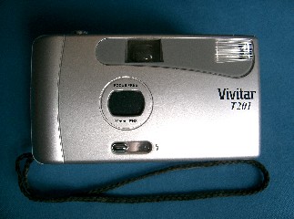
• A disposable camera and a
1.5v AA battery.
• An A4 sized sheet of 2mm thick rigged polystyrene (for making box casing).
• Two 3mm Ø x 25mm screws & six accompanying nuts.
• Standard multi-core copper wire.
• Soldering iron.
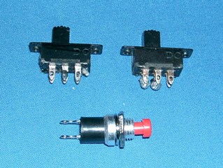
• Two slide switches (on and off positions).
• One push button switch (push and hold for on).
Construction of the
device
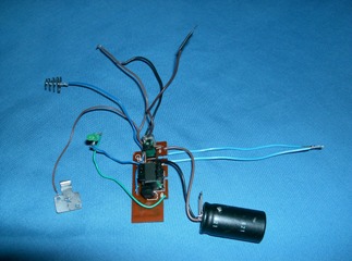
The first thing you need to do is to dismantle the camera. Carefully unscrew any screws and snap apart the camera without damaging the circuit board and its wires or devices. The photos below show my camera before and after it was opened.
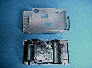
The circuit board should now be Cleary visible. Before taking the board off the camera take a look at where all the wires go and what they are for. Take note on where the charging button operate on the board and where the triggering system is (usually two thin pieces of metal that are mechanically pushed into contact when the ‘take photo’ button is pressed). These are the places where the operating switches of this device will be incorporated.
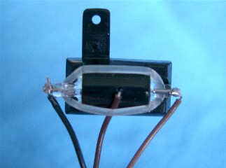
The board can now be removed carefully. The photo below on the left shows the board that came out of my camera. The photo below on the right shows the housing of the flash bulb. The central brown wire on the flash bulb housing shown below can be removed and the end bound with insulating tape (this is the wire that carries a high
voltage of a few thousand volts to ionise the gases in the flash bulb). The other brown and black wires are the wires that will be independently connected to the discharging points of the stun gun (the bolts shown in the photo at the top of the page). The push button switch and one of the slide switches will be connected in series with this circuit line – the slide switch will be a safety and the push button will be the discharge button.
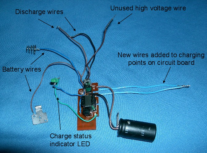
I have labeled this photo with what each wire is for. Click the photo to get a larger photo. I have soldered two new wires from the charging points on the circuit board, these will be connected to the other slide switch as a charging switch, but not yet – the board has to be placed in its box before any of the slide switches can be soldered onto their correct wires. The push button can however be soldered onto the correct wire ready for the other switch to be placed in series with it. The discharge wires will have in series the safety slide switch and the push button switch.
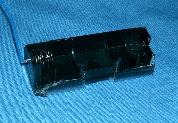
I have managed to salvage the battery holder from my camera and have secured the two connection points (the spring and the plate) which the battery points will press against.
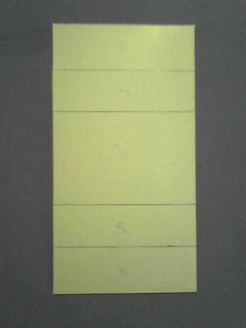
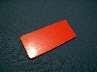
Below are a series of photos showing how I made the box. First of all I estimated the dimensions of the box that would be needed to fit the battery, board, capacitor, switches and wires. I then marked and cut out a strip of the rigid polystyrene sheet as shown in the firs picture below.
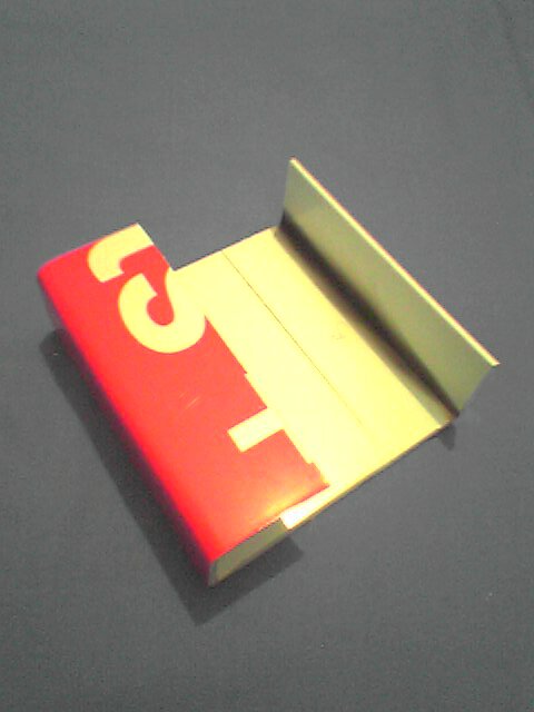
To bend the rigid polystyrene sheet I used a strip heater; you may not have a strip heater but I tried using a lighter and heating along the marked lines, and then bending it back against a ruler worked almost just as well – practice on a few scrap models first.
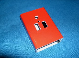
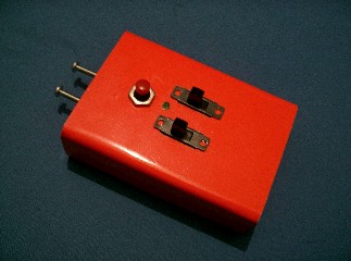
I then used a tensile cement (e.g. Polycement) to weld the end edges together, as shown in the third photo below. The next thing to do was to layout the position of the switches so that they are in appropriate easy to operate and logical positions. I drilled a hole at the top for the push button (discharge switch) and the two slide switch holes below (the safety on the left and the charging switch on the right). I also drilled a small hole in-between these holes for the LED to fit (“capacitor is fully charged” indicator).

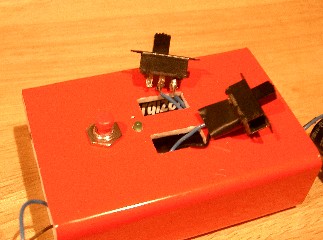
Now this is the slightly tricky bit. Place the circuit board and battery holder in the box (I had the capacitor at the bottom of the box and the discharge leads heading out the top/front) and temporally fix in place with double sided sticky pads (to allow you the replace the battery and to make future repairs or adjustments).
Carefully pull the correct charging wires through the right slide switch hole and the correct wires that will connect to the safety slide switch through the left hole. The two slide switches can now be soldered to their corresponding wires (I had the off positions at the top) and insulation tape wrapped around the soldered points. The switches can be pushed into their holes.
To make the end plates I cut two rectangular pieces of the polystyrene sheet (one can be seen in the photo on the right). I over sized the rectangles and use a craft knife to cut them to the exact size and shape to fit in each end (the box was not quite rectangular).
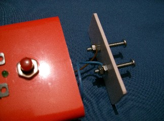
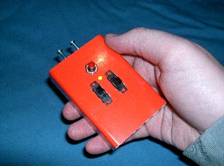
On the end plate at the top/front of the device I drilled two holes and inserted two 3mm Ø x 25mm screws and tightened the bolts to the plate with two nuts on each screw. I then took the two discharge wires (one directly connected to the circuit board and the other passing in series with the safety slide switch and the push button switch) and wrapped the exposed ends of the wire around the screws and tightened another nut on each screw to fasten the wires to the screws.
The two end plates can now be pushed flush with the box and glued using the tensile cement – I applied very small amounts in the corners of the plates to allow me to pull them out with little effort if needed change the battery or make repairs and adjustments.
Hopefully you were able to follow my description and produce a similar device as shown above. If you couldn’t follow my description or have any difficulties then feel free to contact me via my contact page or add a post on my forum.
Using the device
This is just a small guideline to operating the device.
• Turn on the right slide switch to start charging the capacitor - the LED should indicate when fully charged.
• Flick the left safety slide switch.
• Hold the red push button down - the device will discharge between the two bolts when in contact with a conducting surface.