KNSU Rocket

knsu_rocket_1
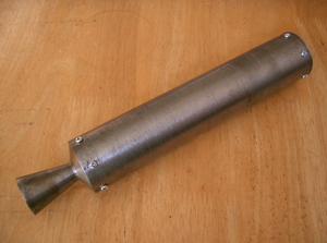
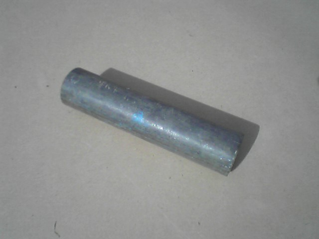
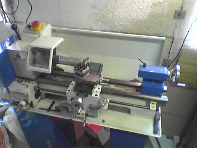
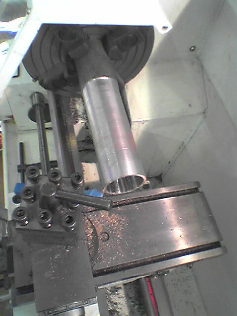
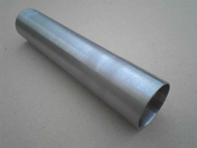
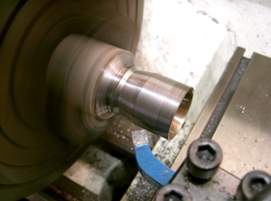
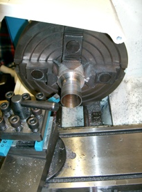
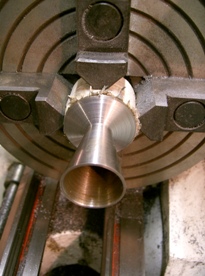
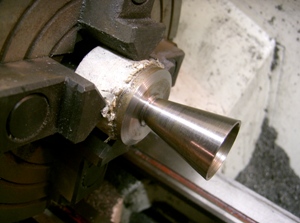
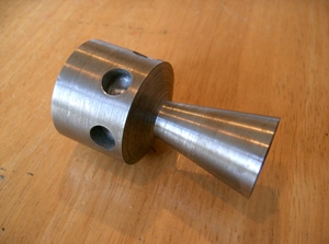
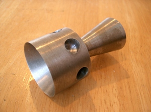
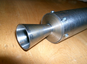
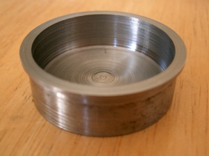
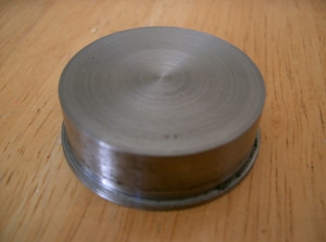
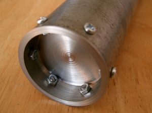
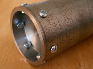
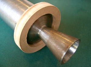
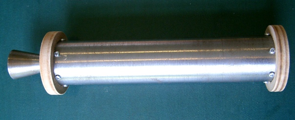
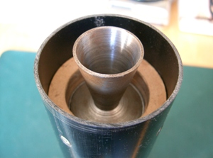
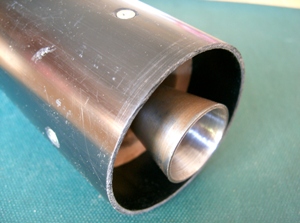
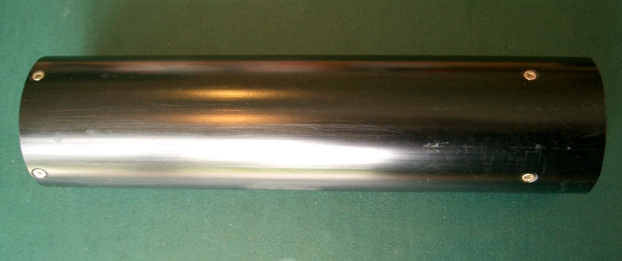
This is an advanced home built rocket that is powered by a solid KNSU propellant. KNSU is a common accronym for the Potassium-Nitrate (KN) and Sucrose (SU) based rocket propellant. The rocket motor housing and nozzle have been machined from steel using a metal work lathe. This rocket should be able to reach altitudes of over 600 meters. This prtoject has been based on knowlage obtained from one of my favourite model rocket websites: Richard Nakka's Experimental Rocketry.


Contents:

Rocket Motor
Rocket Motor Retainment Assembly
Rocket Body
Parachute
Parachute Deployment System
Testing of the Rocket
Launching of the Rocket


Rocket Motor

The rocket motor is based on the design of Richard Nakka's B-200 rocket motor. I have had no previous experience with designing or constructing rocket nozzles or rocket motor housings and decided that I would start with one of Richards more simple and reliable designs. The completed motor and the schematic drawing for my rocket motor are given below.

knsu_rocket_2 knsu_rocket_3


I built this motor in three main stages: firstly I machined the motor housing tube, I then machined the rocket nozzle and fitted it into one end of the motor housing tube; and finally I machined the bulk head end cap and fitted it into the other end of the motor housing tube.

The motor housing tube was made from a short length of scaffolding pipe and machined down to the desired dimentions. The scaffolding pipe was somewhat uneven from its extrusion process and required machineing inside and outside using a standard parting tool for the outside and a boring tool for the inside. The outer diameter is 42.70mm and the inner diametr is 40.30mm (wall thickness of 1.2mm). The length of the motor housing tube is 205mm. The weight of the motor housing tube is 258.0 grammes.

knsu_rocket_4 knsu_rocket_5

knsu_rocket_6 knsu_rocket_7


The design of this rocket nozzle is a conical profile, convergent-divergent, supersonic type. It has a 30 degree convergence half-angle, and a 12 degree divergence half-angle (the same as Richards B-200 nozzle). The throat region is very important in regards to the motor performance - the throat reigion needs to be rounded to avoid a sharp discontinuity to reduce shock losses and to provide a more gradual acceleration of the exhaust gases.

The rocket nozzle was made from a mild steel bar off-cut. Once the work had been machined down to the larger outer diameter, a 9.5mm diameter hole was drilled through the centre producing the correct throat diameter. The 30 degree convergence half-angle was machined first at one end (not shown in photos). After this, the work was taken out of the chuck and inserted back in the other way round. The 12 degree divergence half-angle was then machined. The schematic drawing for my rocket nozzle is given below.

knsu_rocket_8 knsu_rocket_9

knsu_rocket_10 knsu_rocket_11

knsu_rocket_12


To reduce the weight of the rocket nozzle six 10mm diameter holes were drilled 6mm into the side of the nozzle as shown in the schematic drawing and photos. The weight of the rocket nozzle was reduced by 27.4 grammes and now weighs 187.0 grammes.

knsu_rocket_13 knsu_rocket_14


Six equally spaced markings were marked out on one end of the motor housing tube 8mm from the edge. The rocket nozzle was then inserted into this end of the motor housing tube making sure that the weight reduction holes were NOT aligned with these markings. Six 3mm diameter tapping holes (these drill bits have a slightly smaller diameter than a standard 3mm diameter drill bit) were drilled 8mm into the motor housing tube and into the rocket nozzle where the markings were drawn. The holes were tapped and six screws were screwed into the holes securing the rocket nozzle into the motor housing tube.

knsu_rocket_15


The rocket bult head end cap was machined from another piece of mild steel bar off-cut. The outer surface of the bult head end cap was machined first such that a small lip could be incorperated to help provide a better airtight seal and to allow the bulk head end cap to sit flush and straight within the end of the motor housing tube. The item was then turned round and the inner surface was bored out. All the walls of the bulk head end cap is 2mm thick. The bulk head end cap weighs XX grammes. The schematic drawing for my bult head end cap is given below.

knsu_rocket_16

knsu_rocket_17 knsu_rocket_18


Once machining of the bulk head end cap was completed, it was inserted into the the end of the motor housing tube and six equally spaced markings were marked out on the end of the motor housing tube 8mm from the edge (making sure they were aligned with the six crews used for the rocket nozzle). Six 3mm diameter clearence holes were drilled through the rocket motor housing tube and through the bulk head end cap where the markings were drawn. Six 3mm diameter machine screws were inserted into these holes and secured with nuts. This bulk head end cap will be removed to insert rocket propellant (the rocket nozzle will remain secured in the motor housing ube indefinatly).

knsu_rocket_19 knsu_rocket_20


The rocket motor is complete. The total weight of the completed motor is 473 grammes (possibly a little heavy).


Rocket Motor Retainment Assembly

The rocket motor is secured in a motor retainment assembly. This allows a secure yet removable housing for the motor within the main rocket body. It also shields the intense heat generated by the rocket motor when in use from damaging or weakening the main rocket body.

I took a 26cm length of a PVC drainage down pipe with a diameter of 68mm (the same piping used for the main rocket body). I needed to reduce the diameter of this pipe to fit snugly into the main rocket body pipe. To do this I needed to remove an 11mm stip from the diameter of the pipe, reducing it from a 68mm ext. diameter pipe to a 64mm ext. diameter pipe. I used a long bladed saw to cut a straight along the length of the tube and another 11mm apart form the first. The pipe then had a strip section missing. After testing if closing the pipe made it the correct diameter, the pipe was closed and solvent welded together making sure the edges were flush and straight.

A blanking plate was needed at one end of the motor retainment tube. A 10mm thick circular disc was cut from a board of fire retardant MDF (see top left disc in photo below). The disc was sanded around it perimeter untill it fit snugly into the end of the motor retainment pipe. To secure the blanking plate, four equally spaced 3.5mm diameter pilot holes were drilled 10mm through the tube and into the sides of the blanking plate. The holes in the tube were counter sunk to allow a flush surface once screws were inserted to fix the blanking plate in place. Four 10mm long wood screws were used.

knsu_rocket_21 knsu_rocket_22

knsu_rocket_23


The motor retainment rings comprised of three 10mm thick rings cut from fire retardent MDF board (see rings in photo above). The rings had an outer diameter of 64mm such that they fitted snugly into the retainment tube. The hole in the middle has a diameter of 40mm and such that the ends of the rocket motor fit snugly into them up to the bulk head and nozzle retainment screw heads. One of the rings is push fitted onto the bulk head end of the rocket motor another onto the nozzle end of the rocket motor.

knsu_rocket_24 knsu_rocket_25

knsu_rocket_26


The rocket motor (with the two retainment rings attached) was slid down into the retainment tube (bulk heand end first) until it was firmly up against the blanking plate. The third retainment ring was then slid into the retainment tube until it was firmly up against the nozzle end retainment ring. The reason for adding this ring is because the mounting screws can be fixed into this ring as opposed to the retainment ring that is in direct contact with the rocket motor which will get very hot when in operation and hence could be weakened. Four equally spaced 3.5mm diameter pilot holes were drilled 10mm through the tube and into the sides of the third retainment ring. The holes in the tube were counter sunk to allow a flush surface once screws were inserted to fix the retainment ring in place. Four 10mm long wood screws were used.

knsu_rocket_27 knsu_rocket_28

knsu_rocket_29


The rocket motor retainment housing is nearly complete. It needs to be fix into the main rocket body using two more retainment rings. These rings are slightly larger in ext. diameter to fit into the main rocket tube.

knsu_rocket_30 knsu_rocket_31

knsu_rocket_32


Rocket Body

The rocket body is made from a PVC drainage down pipe with a diameter of 68mm. A 130cm length of this pipe was cut to form the main rocket body.


Parachute

Coming soon...


Parachute Deployment System

Coming soon...


Testing of the Rocket

Coming soon...


Launching of the Rocket

Coming soon...